Click Bond · Quality Engineering Internship · 2026
Atlas Copco Cycle Testing
I improved a manual five-bolt torque-cycle test and designed the next-stage motion system to automate it.
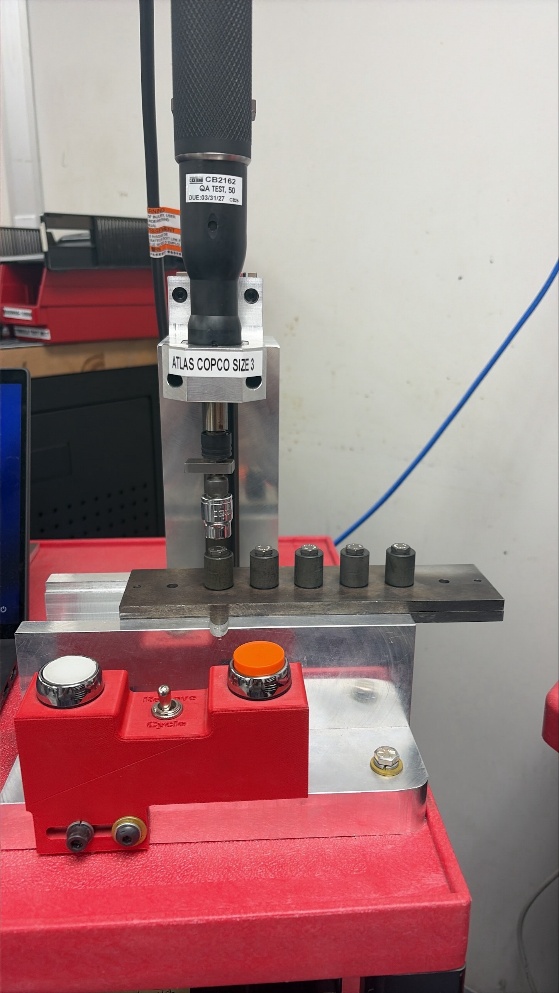
The problem
Five bolts, repeated cycles, too many manual steps.
The Torque Control Unit stayed in one position while a technician moved the nut-channel fixture, aligned each bolt head, and ran the tightening and loosening steps. Exporting data and preparing the test report added more work after the test. I started by observing that workflow and asking technicians which steps were slow or unclear.
My approach
I separated the work into improvements we could use immediately and a longer-term automation concept. Learning the controller's existing capabilities first prevented us from designing hardware to solve a software or training problem.
Project facts
- My role
- QA intern, test process and mechanical automation design
- Test
- Five bolt positions across a 50-cycle specification
- Built
- Report workflow, 15° socket rotation, calibration fixture and procedure
- Designed
- PLC-controlled X/Z motion and bolt-seating logic
Implemented improvements
Make the existing test easier to run.
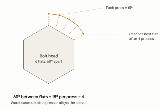
I changed the reporting workflow so a technician could download the controller's install and removal data, then generate the formatted report with one button. I repaired the workbook's pass/fail logic and extended it to cover the full test sequence. For bolt alignment, I programmed a second tool button to rotate the spindle 15° on demand.
In that trial, I completed 10 cycles in 20 minutes. These are observed results from a trial, not a claim that the entire 50-cycle test or future automation system was completed in that time.
Mechanical engineering focus
A motion concept built around the test sequence.
Move the tool, keep the fixture fixed.
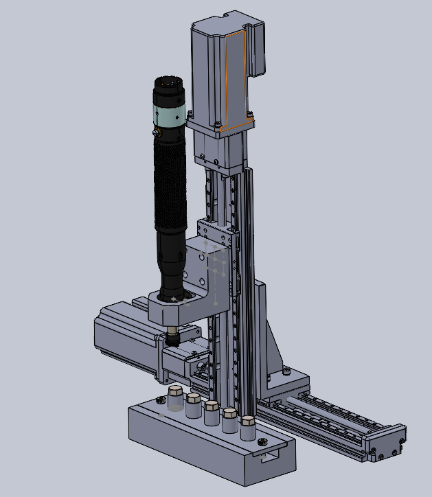
I modeled an X/Z system in SolidWorks so the screwdriver could travel between bolt positions and lower onto each bolt. A stationary nut-channel fixture simplified the proposed layout and kept the workpiece in one location.
The design called for a ball-screw X axis to carry the Z assembly with low backlash. I selected a lead-screw Z axis for its resistance to back-driving when power is removed. This was a design choice, not a tested safety claim.
Account for alignment and failure.
Position alone would not guarantee that the socket seated on a bolt head. The Phase 4 design added a proximity check: if the spindle had not seated, the controller would retract, rotate, and try again before tightening.
I also mapped home sensors, tool status signals, a technician decision point after a failed bolt, and an emergency-stop requirement into the proposed control sequence. These elements remained part of the design, not deployed hardware.
Check calibration as part of the system.
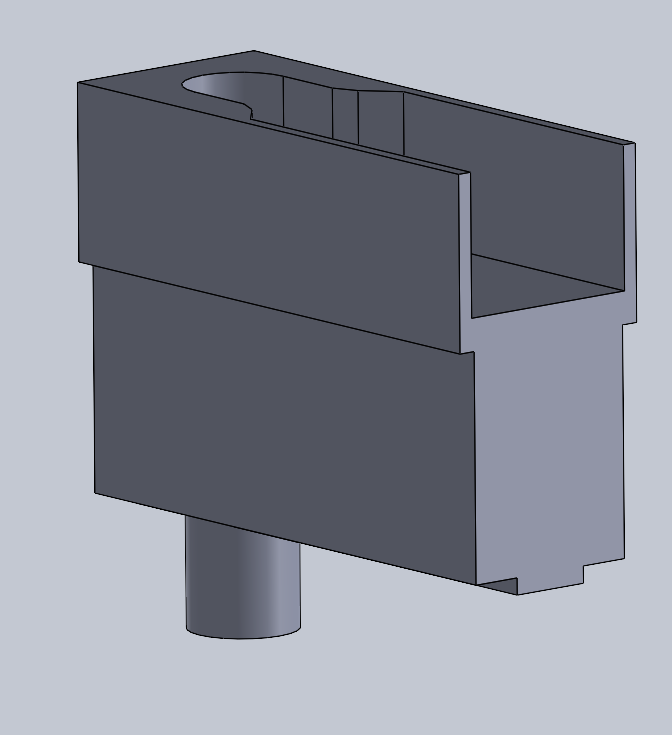
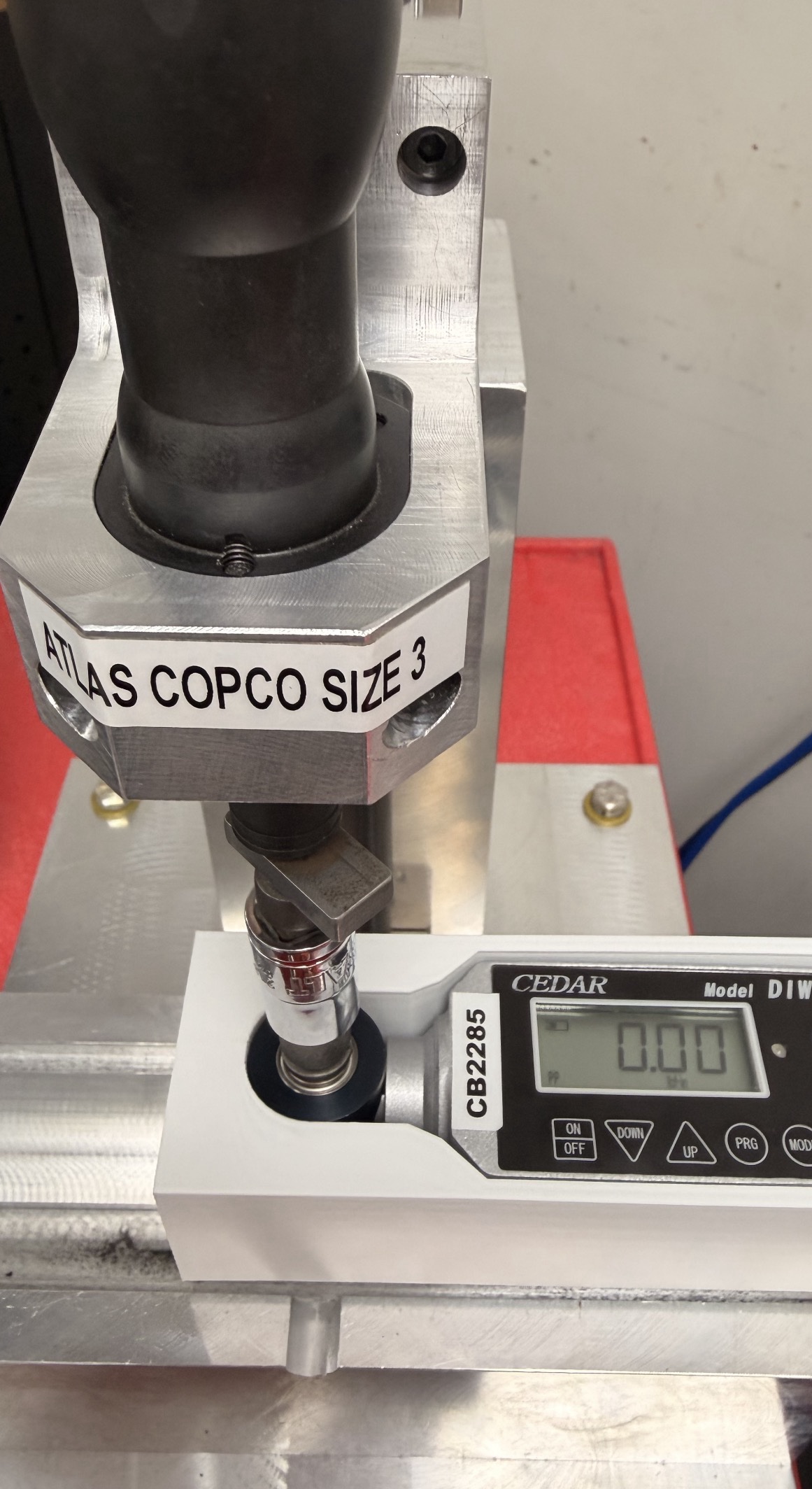
I designed and 3D-printed a holder for the digital torque wrench used to check the screwdriver. The first calibration trial showed that the holder could shift, which gave me a concrete issue to address in the next fit revision.
I documented the calibration steps so another technician could repeat the process consistently. The fixture work reinforced that a CAD fit needs to be checked against the real tool and mounting setup.
Project scope
What was delivered, and what remained a design.
Report generation, workbook logic, calibration procedure, and test startup.
Technician-triggered 15° socket rotation.
PLC-directed X/Z motion while the technician handles alignment and starts tightening.
Sensor-guided retract, rotate, retry, and sequential test logic.
Engineering takeaway
Improve the process before automating it.
The immediate reporting and control changes made the existing station easier to use. The SolidWorks model and control plan then gave the team a defined path toward automated motion, with the remaining build and validation work clearly identified.