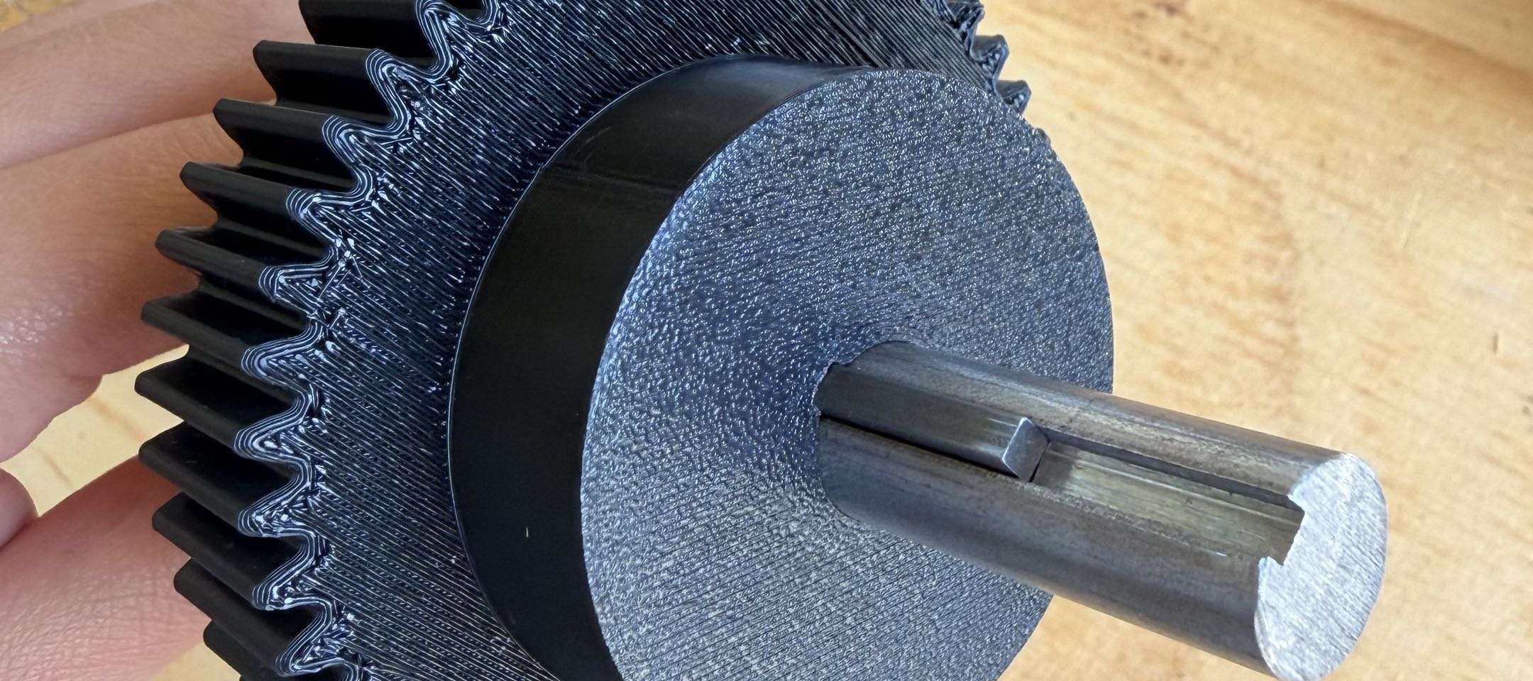
Printed gear keyway
The report links the early failure to material removed while sanding the undersized bore. The test showed that a nominal gear-tooth strength calculation did not capture this printed hub and keyway weakness.
Mechanical design · ME 329 · Cal Poly
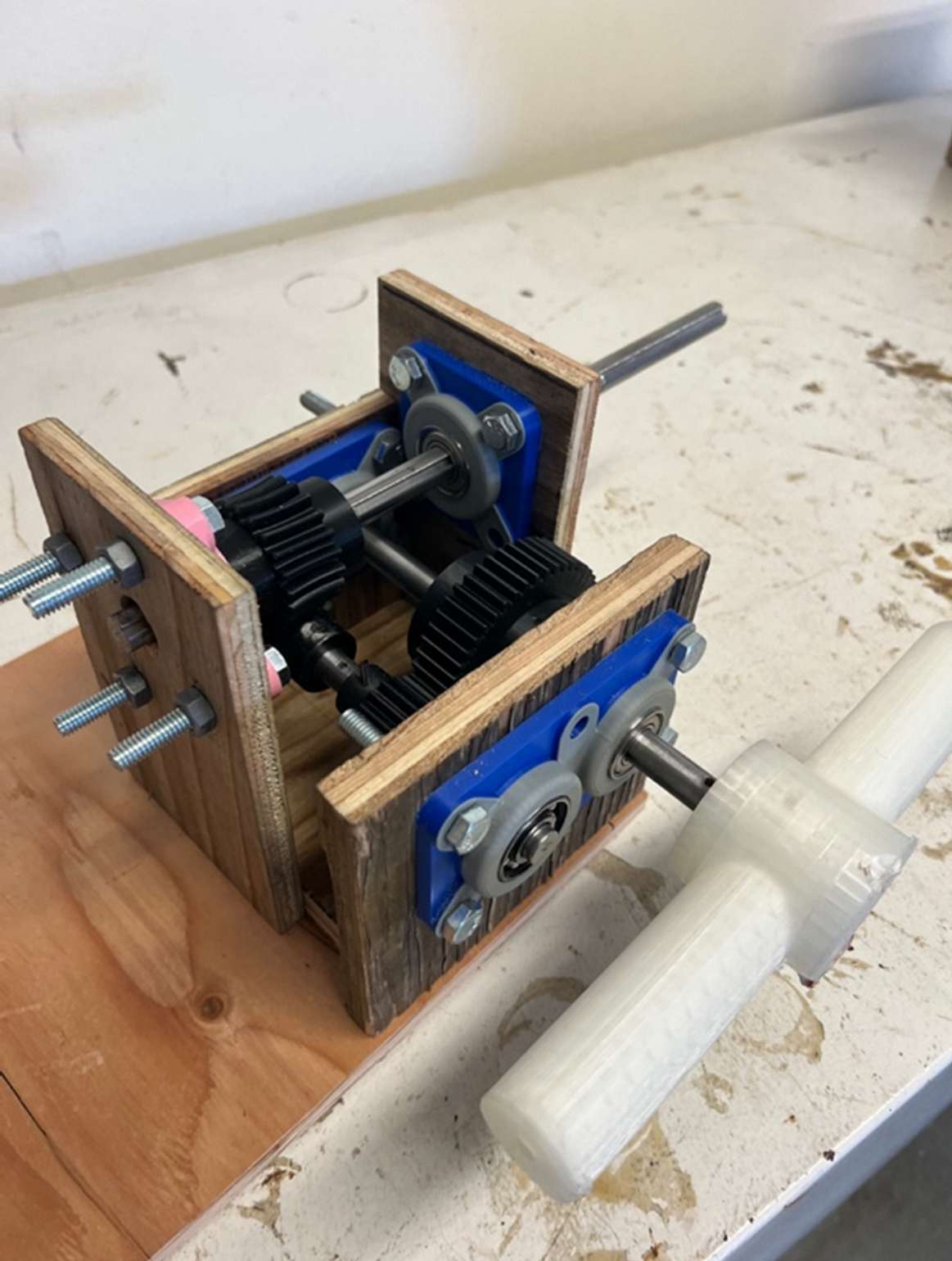
We designed and built a worm-and-spur gear train to lift a 20 lb load by hand. The prototype moved the load; testing then revealed where the printed gears and axial retention needed a stronger design.
My contributions: CAD, engineering calculations, machining, and prototype testing.
Design challenge
The gear train needed enough torque to raise a 20 lb load while keeping manual input within the project limit. The team chose a worm stage for high reduction and load holding, then a spur pair to transmit motion to the output shaft.
Engineering process
Positioned the worm, spur gears, shafts, and bearing mounts within a compact housing.
Used Goodman shaft calculations, an AGMA gear model, and bearing and bolt checks as design tools.
Machined shafts and fitted printed components. Undersized printed bores prompted a 0.008 in allowance and reprint.
Hand-cranked the assembled prototype, observed load motion, and documented the failure points.
CAD and fabrication
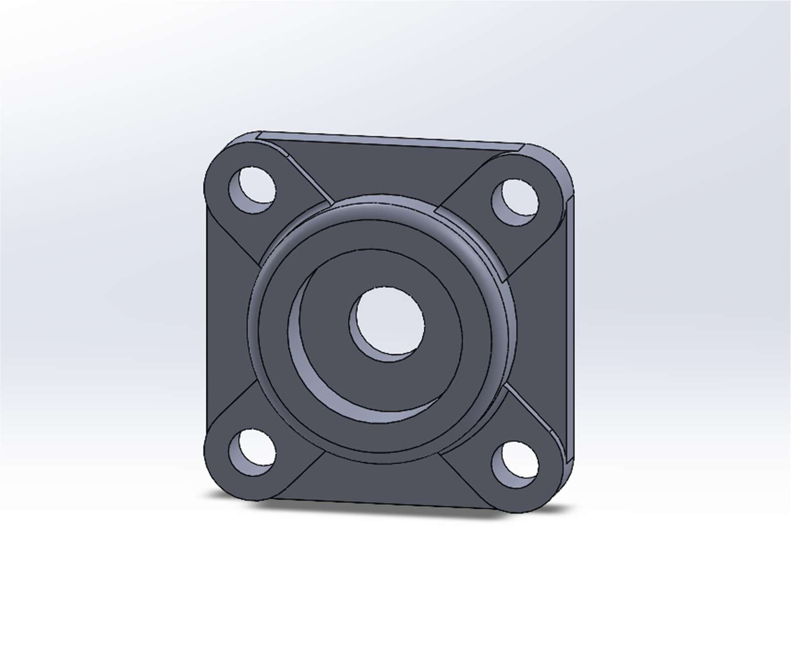
CAD helped define support geometry and component placement before fabrication. A bearing housing had to locate the shaft while leaving room for fasteners and the adjacent drivetrain.
During assembly, the printed bores came out undersized. The team revised the fit allowance and reprinted parts—an early reminder that nominal CAD dimensions do not guarantee an assembled fit.
Manufacturing lesson: check critical fits on physical parts before relying on them in a loaded mechanism.
Prototype test
The assembled train lifted the test load and transmitted motion through the drivetrain. At the highest applied torque, the printed 48-tooth spur gear's keyway failed. When load direction reversed, the worm wheel shifted because its axial restraint worked in only one direction.
The report links the early failure to material removed while sanding the undersized bore. The test showed that a nominal gear-tooth strength calculation did not capture this printed hub and keyway weakness.
The wheel stayed positioned during lifting, then moved axially when the force direction changed. Retention needed to account for both directions of operation.
What I would change
Team project with Aidan Dilworth, Ian Kaabi, and Kenny Heilsberg. Images are from the team's ME 329 final report.